Customer Interfaces
This section explains how to set up a customer interface.
Video Tutorial
We created a video tutorial demonstrating these steps. You can find the video here in our YouTube channel. As always, the full catalog of video tutorials is here.
Database Overview
To fully understand how IXP Manager treats customer interfaces, you need a little background on the database schema. This will also help explain why we have laid out the UI as it is.
The original database schema dates from pre-2005 and has stood the test of time extremely well.
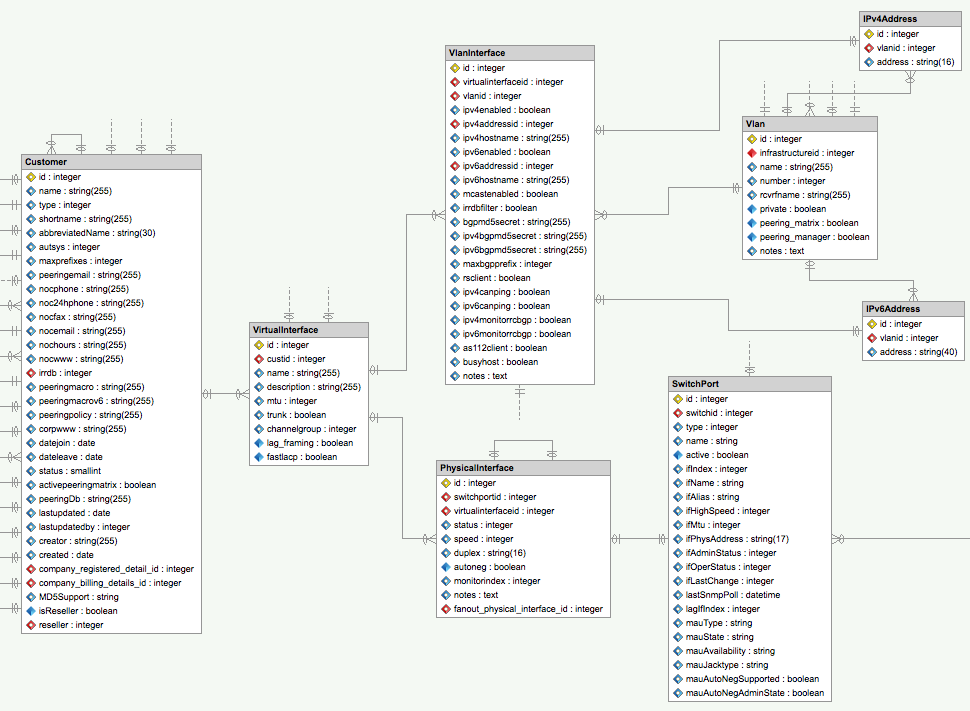
The above is described as follows:
- Customers have a 1:n relationship with virtual interfaces (VI). A VI is a container object that represents a customer connection and all the elements that make up that connection.
- VIs have a 1:n relationship with physical interfaces (PI).
- A physical interface in turn has a 1:1 relationship with switch ports (SP).
- PIs represent what we say the customer has (e.g. a 1Gb port). The SP has information from the switch itself and can help identify inconsistencies with what was expected to be configured/billed and what has actually been provisioned).
- PIs can also move between SPs (e.g. customer upgrades / switch replacements / etc.).
- By schematically representing PIs and SPs as different entities, we can associate elements such as usage graphs to the PI so these remain consistent when a SP changes.
- Adding a second (or more) PI to a VI indicates that the port is a LAG.
- VIs have a 1:n relationship with VLAN interfaces (VLI). You can consider the PI element the layer2 / physical element and the VLI element the layer3 element.
- A VLI has a 1:1 mapping with a VLAN (typically the peering LAN).
- If IPv4 is enabled, the VLI has a 1:1 mapping to an IPv4 address from the given VLAN.
- If IPv6 is enabled, the VLI has a 1:1 mapping to an IPv6 address from the given VLAN.
- The VLI also indicates if this interface should have a route server peering session, MD5 passwords, etc. (all explained below).
Provisioning an Interface via the Wizard
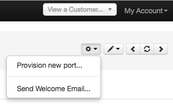
The best way to provision a new interface for a customer is to use the wizard. This can be accessed from the customer's overview page via a menu on the top right:
When you open the wizard, you will see:
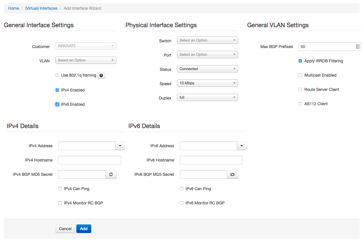
This can be used to provision a single port standard customer connection. If they customer needs a LAG or other non-standard options, these can be added afterwards.
General Interface Settings
The customer should be prefilled and read-only as you enter the wizard from a specific customer overview page.
You would normally just select your main / primary peering VLAN from the VLAN dropdown. There are some notable exceptions:
- you may have more than one peering LAN. For example, INEX runs two resilient peering networks in Dublin and a separate regional exchange called INEX Cork. These are all unique VLANs.
- if you are provisioning a port dedicated to a private VLAN, you would just select that VLAN but leave IPv4 Enabled and IPv6 Enabled unchecked as IP addressing on private VLANs in not within an IX's purview.
- at INEX we also have quarantine VLANs for each peering VLAN. You would typically not select a quarantine VLAN here during provisioning unless you are using automation. Just put the interface in the primary peering LAN and let the Physical Interface Settings (see below) look after the quarantine flag.
- You should check the
Use 802.1q framingcheckbox if the port should be tagged facing the customer. If you are not using any automation tools, this will be informational for you rather than production affecting. - Checking either or both of IPv4 Enabled and IPv6 Enabled will show the IPv4 Details and IPv6 Details (as per the above image) and enable these protocols for the customer's connection.
Physical Interface Settings
This section allows you to select the physical interface / switch port for the connection.
Switch: a dropdown list of all switches. Be careful as at present this list is all active switches rather than switches on the same infrastructure as the selected VLAN from General Interface Settings.Port: the switch port to use. This is dynamically populated when the switch is selected and will only show ports of type Peering or type Unset / Unknown (these are set on a per port basis when adding / editing switches).-
Status: the port status currently has one of five options. They effectively work as a boolean where Connected means on/enabled and the rest mean disabled as explained below. In practice, we tend to just use three states: -
Connected: this is the most important. When a virtual interface has any port with the Connected state, then IXP Manager will consider this connection active and will generate router configuration, monitoring configuration, etc. Awaiting X-Connect: the customer has requested an upgrade / new port and we are awaiting for the co-location provider / customer to get the cross connect organised.Quarantine: the port is connected and is under going quarantine prior to being moved onto the production peering LAN. During quarantine, INEX checks the port to ensure only ARP, IPv4 and IPv6 packets are received (no *-discovery, STP, etc. as well as a number of other things).
The Not Connected and Disabled states have the same effect as (2) and (3) above and can be used as informational settings where (2) and (3) do not apply.
Speed and duplex are self explanatory. These settings in the physical interface entity are informational unless you are doing automation. They also have knock on effects to (for example) graphing - where the MRTG max value on an interface is set to this to prevent weird excessive spikes on counter rollovers.
General VLAN Settings
These settings apply to the VLAN interface.
The Max BGP Prefixes is a setting used to determine max prefixes on router BGP peers - please see the global version of this as explained in the customer section for details.
If Apply IRRDB Filtering is not set, then the route servers will accept any prefixes advertised by the customer (note that the default templates will filter martians and apply a max prefix limit). Generally speaking this is a very bad idea and should only be used in exceptional cases. INEX never uses this setting - but demand from other IX's had it added.
Multicast Enabled is informational only. INEX used to support multicast on the peering LAN but removed support in 2015 due to lack of interest and added complexity / cost when purchasing new switches.
If Route Server Client is checked, then IXP Manager will configure a BGP peer for this connection when generating route server configurations. It is also used in other areas to show if a member uses the route servers or not, by the Peering Manager to calculate missing BGP sessions, etc.
Similarly, if AS112 Client is checked, then IXP Manager will configure a BGP peer for this connection when generating AS112 router configurations.
IPv4/IPv6 Details
When IPv4 / IPv6 Enabled is checked under General Interface Settings above, these two sections will be available.
The same details apply to IPv4 and IPv6 options so we will document them together.
IP Address: the IP address to assign to this customer. This is taken from available IP addresses for the VLAN selected in General Interface Settings.- IP addresses are added in IXP Manager via the left hand menu under IXP Admin Actions.
- The dropdown also works as an input field - this allows you to enter a new IP address that does not already exist in the field. When the wizard form is submitted, the address is added and associated with the VLAN. This is most useful for the IPv6 field if you are using a non-sequential numbering plan.
Hostname: if you use IXP Manager to configure your DNS ARPA entries, the hostname entered here will be returned when a PTR request is made for the assigned IP address. Enter a complete hostname without trailing period such as:www.example.com.BGP MD5 Secret: The will be used for generating router configurations.- The circle refresh icon in the IPv4 section will generate a cryptographically secure secret in modern browsers.
- The square refresh icon in the IPv6 section will copy the value from the IPv4 section.
- Note that setting a MD5 here does not mean that all router configurations have to include it. MD5 can be disabled entirely by a routers configuration or by templating.
Can Ping: IXP Manager generates configuration for a number of other tools such as Smokeping and Nagios which ping customer routers. These are invaluable tools for problem solving, monitoring and graphing long term trends. We enable this by default unless a customer specifically asks us not to.Can Monitor RC BGP: this is more of a legacy option for configuration builders that used to check for established route collector BGP sessions and warn if not present. This is deprecated and will be removed.
If you wish to make Hostname above optional, set the following .env configuration option:
IXP_FE_VLANINTERFACES_HOSTNAME_REQUIRED=false
Viewing / Editing an Interface
Once an interface has been added as per the above wizard instructions, you can view and edit the interface by selecting the edit icon against the connection you are interested in from the Ports tab on the customer overview page. When you do that, you will see a screen such as the following:
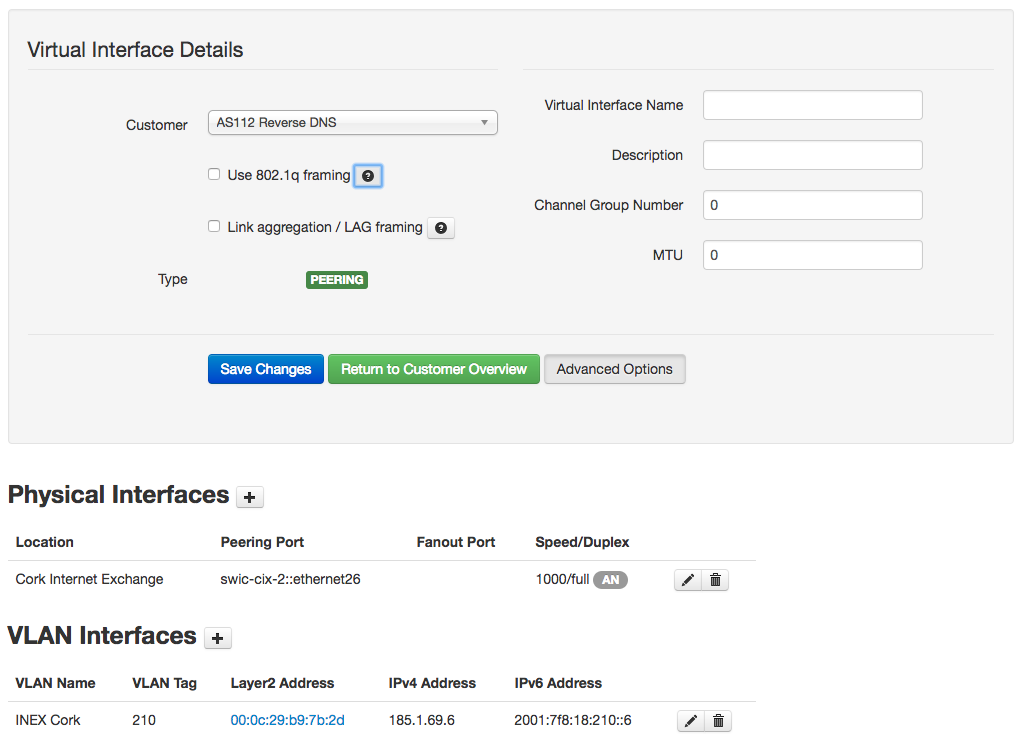
You can see from the layout of this screen how it ties in with the schema explained above.
Virtual Interface Details
The screenshot above shows the virtual interface details with the Advanced Options shown. The additional fields here that were not in the wizard are described below.
Link aggregation / LAG framing is mostly informational unless you are doing automation. There are some restrictions. Namely / specifically:
- if you have more than one physical interface, it will require you to set this.
- for a single interface, checking this indicates you want LACP on a single member LAG. This is useful and often common practice as it allows upgrades without outages.
The Virtual Interface Name is again mostly informational unless you are doing automation. It should be the start of the LAG name without the number. On an IOS device this would be Port-channel for example. Matched with this is the Channel Group Number with is tacked onto the end of the Virtual Interface Name. Leave it as 0 and when you check Link aggregation / LAG framing and save the changes, IXP Manager will set this to the next available unused port channel / bundle / LAG number on that switch.
Both Description and MTU are informational.
Physical Interfaces
You can add additional physical interfaces to a connection / virtual interface. This effectivily means you are creating a LAG. The form for adding additional physical interfaces is identical to that in the wizard.
VLAN Interfaces
The most common use case of more than one VLAN Interface is when your customer may also have private VLANs on their connection.
Other than that, the VLAN interface add / edit form has all the same elements as the wizard with one addition:
Busy host: this flag indicates that the customer's router is unusually slow to reply to ICMP echo requests and that when monitoring, the configuration should allow for warnings after a 5sec RTT rather than 1sec.
Partial Port Speeds / Rate Limiters
In cases where the IXP provides subrate connectivity, the declared port speed at an IXP may not match the port speed which is configured on the access device. In these cases, please use the rate limit feature:
- New
rate_limitcolumn on the database as the actual request for partial port speeds is really a request to honour rate limits on ports. If there are other use cases this can still be used, the actual physical (production) effect is determined by how individual IXPs use this information in their provisioning systems / as they manually configure switches. - Rate Limit field when adding and editing a physical interface through the normal virtual interface overview. NB: this means if using the New Interface Wizard, you configure the physical speed and then edit the physical interface afterwards. The wizard is meant to cover the 90% scenario and we'd prefer to keep it de-cluttered.
- This is for member ports; not core ports.
- Speed reported on various member screens as the rate limited speed (and sometimes, where space / appropriate) as x / y and also GUI labels to make it clear when a port is rate limited.
- IX-F Member Export now reports rate_limit speed and adds an IXP Manager specific field called if_phys_speed to show the physical port speed.
- The switch configuration viewer (e.g. INEX's one also updated to support this.
- Port utilisation updated to be congnisant of this.
- Switch provisioner yaml/json output now has rate_limit for peering ports, null means not in use.
- MRTG configuration has not been updated as the MRTG config uses the detected speed from SNMP. We currently do not see any value in swapping this for the rate limited speed as rate limiters can be buggy / misconfigured / etc and we'll want to see that traffic.
- The dashboard statistics also reflect this and include a new section at the end which shows how partial ports were accounted for.
- The physical interface list (left hand menu -> Interfaces -> Physical Interfaces) has a rate limit column to make it easy to see the rate limited ports.